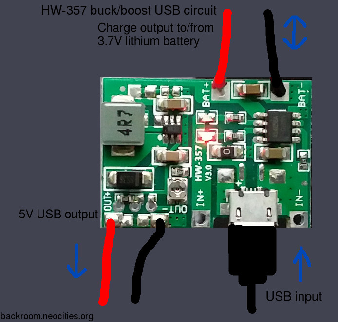
above: My chosen battery supply circuit.
Home Go back.
KIG workshop Back to the main KIG page.
Misc. Raspberry Pi mods and projects
Setting the filesystem to Read Only
A basic UPS
There are a few Pi UPS boards available. Some work, but most of them seem to be designed to run through the GPIO pins. As the GPIO layout has changed over time, this immediately means that your choice of UPS will depend on what version of Pi you have and what is still available (and has been documented to work). This project is completely transparent to the Pi, it runs entirely between the power supply and the Pi itself. This means the Pi won't know, so it won't be able to report the power status or take any action based on that. The block diagram looks like this:
5V Power supply -> UPS project (and fuse) -> Pi
The idea is to maintain a 5V supply (from a lithium battery management system) at a suitable level of current to keep everything going until the regular supply comes back online. I'll start with a simple/bad design and refine it from there.
First idea: The USB cable connects to a lithium cell charger circuit. This is connected to a lithium cell (an 18650 or similar). Power is taken from the cell charge terminals to the Pi. This is not the best idea, as the Pi will only see (at best) 4.2V from the cell. In my experience of testing this for very short time periods (ca. 20 sec), the Pi remains functional albeit with noticeably dimmer LEDs. This system is likely to cause unpredictable faults with the Pi and any connected equipment, and probably within a very short space of time. When the incoming USB power is on, the Pi is powered from the cell charging system. This does mean that, if a low current supply is used, the lithium cell will probably never reach a float/full charge status. This never-quite-full status should improve safety as the cell will not be at risk of continued float charge should the control BMS fail to cut off. When the USB power cuts out, the Pi immediately draws power from the lithium cell, at reduced voltage. As mentioned above, this is highly likely to cause faults, depending on the load of the Pi. When power is restored, the LEDs return to their full brightness and normal operation is, in theory, restored. If a high current power supply is used, it's quite likely to fully charge the cell despite the additional load of the Pi, and this would cause the charge system to cut off/ back on regularly. It's not ideal, although it might be possible to mitigate the effects of these voltage fluctuations to some extent by adding another smoothing capacitor across C6 on the Pi (another project).
WARNING: If your Pi has been modified to provide a direct DC power bus between the power input and USB port output voltage pins, it's possible this will also be feeding power back into the Pi (if a powered USB hub is used). Whilst this is one way of powering the Pi, it runs the risk of feeding 5V back down the power cable and into whatever lithium cell you're intending to draw power from. Assuming a worst-case scenario where the internal diodes have been bypassed/shorted, this is a bad idea. It's possible to add a diode in series with the lithium cell, but this reduces the input voltage even more.
Second idea: Using a buck/boost circuit from something like power bank would allow for a closer approximation of 5V to be supplied to the Pi. The buck/boost circuits drop the incoming 5V down to whatever it deems the lithium cell needs, charge it, and then boost the cell voltage back up to 5V (or similar) to run the desired load/s. The key factor here is what delay, if any, there is between cutting the incoming power supply and starting the boost/output circuit. In power banks, switch-on time isn't particularly important as long as it comes on at some point. It's critical in a UPS application though, and waiting around at 0V for half a second or more is not acceptable. Some power bank boards can run online whilst charging, in a similar way to some mains UPS systems. Unfortunately much of the sales literature fails to specify this sort of information because, in their intended use cases, it's just not important. It may be possible to ride over this power loss using capacitors, but this will depend on how much load the Pi is under (and how much current the local boost circuit is capable of providing from a black start- some will simply cut out if the startup load is too great). The solution I chose uses a Lithium charging PCB with on board buck/boost circuit which is permanently active, and is shown in the picture below:
above: My chosen battery supply circuit.
Third idea: My chosen solution combines both the first and second ideas, and is shown above. A USB-> lithium charge circuit is used to charge a lithium cell, as in the first idea. The cell terminals are connected to a separate boost circuit, which is running constantly to create the 5V which is delivered to the Pi. This eliminates the risk of changeover dropouts because the 5V generator circuit will be running all the time. It also has the advantage of providing a regulated 5V output regardless of the cell input voltage. By virtue of the fact the cell is constantly running under load, it also reduces the chances of reaching full status. This means the risk window presented by a fully charged/semi-floating lithium cell should not arise.
A side note: Buck/boost converters can sometimes produce a noticeable sound caused by the magnetostriction of the inductor coil/s whilst in operation. With other background noise this shouldn't usually be noticeable but in a quiet environment it may be, and its high frequency nature has a tendency to be both directional and reflective. It may be advisable to place these units away from sleeping areas (for humans and pets) to help ensure a noise-free sleeping experience.
Setting the filesystem to read-only:
Making the filesystem read-only can improve relliability, assuming you don't need to make arbitrary changes to the system configuration. You can do this by entering raspi-config and first selecting "Performance Options", shown below:
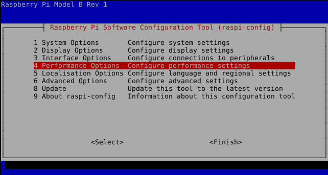
above: raspi-config read-only step 1
Then select "Overlay File System":
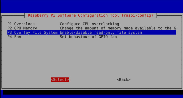
above: raspi-config read-only step 2
Make sure you make all your system changes first. You'll need to get everything set up exactly as you want it to be on boot, because locking down the SD card means any changes you make from then on either won't be possible or won't be remembered. It's always possible to undo this setting if you need to update anything, remember to re-apply it again afterwards though. I should probably mention that applying the read-only tag on the SD card is a bad idea, simply because the Pi won't be aware of this flag and will continue to try and write out to the card.
Reduce latency in Firefox:
Modern versions of Mozilla Firefox include an accessibility layer called Firefox Accessibility Service, and this is designed to enable the use of various functionality enhancements, security tools etc. Unfortunately this also adds latency to various actions like typing. On a Raspberry pi (and other computers) this may be very noticeable. It's possible to disable the Accessibility Service, and doing so can make a real difference in the responsiveness of the browser. Doing this will also break anything that uses the service, so it's worth checking it's not needed by anything first. To disable the service, enter about:config and type accessibility.force_disabled. Set the value to 1.
Another performance hack in Firefox is to disable the transitions and animations that use system resources. Once again, head to about:config, and this time type ui.prefersReducedMotion. Create a numerical string with this name, and set the value to 1.
BANG, and the animations are gone! (For now.)