This is the KIG radio page. All the radio-related things will be here.
Various C.B. radio hacks and repairs [work in progress, pictures to add]
First, some information about Idiot Diodes. Sometimes they've been replaced so many times that the PCB tracking is damaged, and it's no longer possible to add the diode in the usual way. In this case, it may be necessary to make a surface-mount repair on the board itself. This can be straightforward, depending on the density of the board layout. Standard 1N4001 diodes can be used. In this case, it's important to make sure the diode (or wiring) doesn't come into contact with the case of the radio. Whilst the diode case itself is not conductive, space between the diode and the case would be good practice. Some insulating tape could be used where the gap is minimal but the repair in this way is unavoidable.
What's an SMA connector and what isn't?
There are two connectors which, to the untrained eye, may appear to be both SMA. They share the same thread, and an SMA antenna will, technically, fit the Not SMA socket (although equipment configured in this way should never be used). The connectors are both electrically different though, as the pictures below will hopefully demonstrate. The picture to the left shows an antenna with an SMA connector, and a non-SMA is to the right of it:
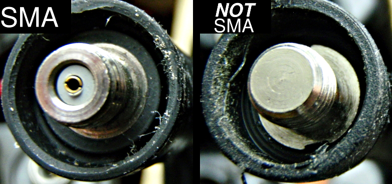
Comparison of SMA and non-SMA RF antennas
The two antennas (antennae?) above are different only in their connector. The picture below shows an undamaged SMA socket to the left, and to the right an SMA socket which has been destroyed by the force-fitting of a non-SMA antenna:
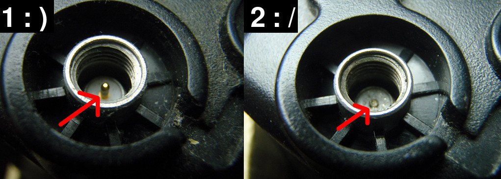
Undamaged SMA connector (left), damaged connector (right)
This is a common failure, resulting in the central pin (the RF carrying element) no longer making contact with the corresponding part of the correct antenna connector once refitted. This is probably caused by someone trying to fit the non-SMA antenna, assuming all SMA-like connectors are equal. This results in a low/no output fault from the radio under test as, initially, a direct short will be created across both the RF connector and the outer gound. This risks damaging the radio further, and it's possible by this time the pin has been pushed irreversibly into the base of the socket meaning it won't make contact with the correct antenna contact again. All too often the fault requires replacement of the entire antenna connector component, which is not always an easy task!
Home Go back.