above: Guessing the polarity of the case
Home Go back.
KIG workshop Back to the main KIG page.Using an 18650 lithium cell in the Polish W3-P mine detector
This adaptation is completely reversible, and requires no modifications to the device in any way.
This part relates to an ex-Polish army mine detector. I was looking for a cheap metal detector to find some tools I'd lost in a field. The W3-P just happened to be the cheapest metal detector I could find, and it's really well made. The downside is that it seems to use cells which are hard to obtain (at least here in the U.K.). In order to make this detector work (assuming it does), the following diagnostic steps need to be undertaken:
1> Work out the polarity of the case;
2> Try to work out an acceptable operating voltage, given the size of the battery compartment and the age of the device;
3> Either create a power supply, or find a cell/battery which can be made to fit inside.
above: Guessing the polarity of the case
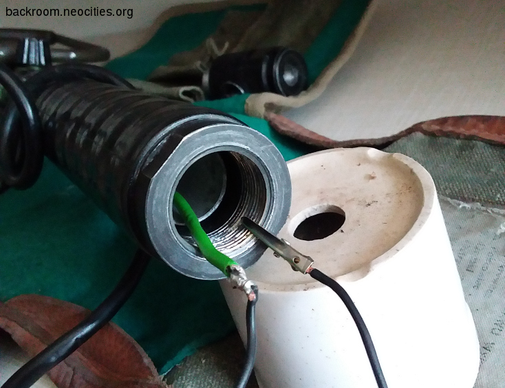
I assumed the end cap of the battery terminal was negative, with the inner centre post being positive. The battery compartment is slightly wider in diameter than a AA cell, but not wide enough for D cells (I haven't tried C cells as I don't have any). An 18650 lithium cell (approx. 4V) will fit, but there is room to spare at the end. I decided to create a spacer to fit behind the 18650, connecting it directly to the end cap switch, and to the outer case. The detector started making noises, at a volume level that was suitable for my use. The cell ground extension spacer was made from a piece of wooden dowel with screws in each end, connected with a wire running along its length. One of the terminals of the cell spacer is shown in figure 1, below:
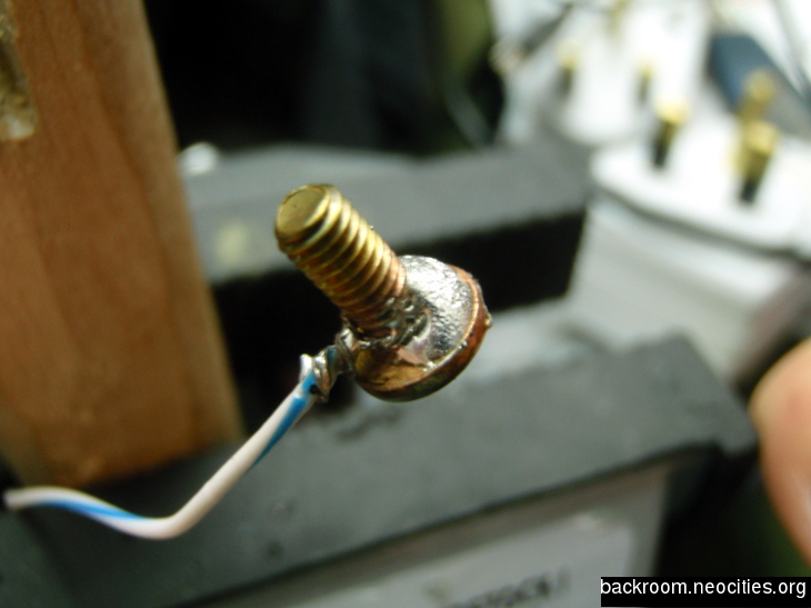
above: Showing brass terminal of cell spacer.
The brass screws fitted into the ends of the dowel. They protruded enough to connect to the cell on one end, and the end cap/power switch on the other. One of the screws is shown in situ, in figure 2 below:
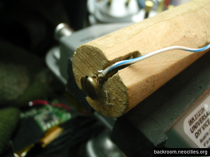
above: Showing brass cell terminal in situ.
The completed assembly is shown in figure 3, below. The diameter of the dowel was slightly too wide to fit with the wire running alongside, so an edge was shaved down to enable to wire to travel without rubbing on the inside face of the battery tube.
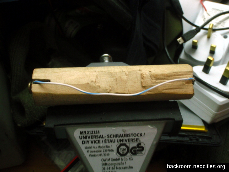
above: Showing completed cell spacer.
The detector works well on a single 18650 at around 4V, which is probably about what would have been provided by the original batteries.
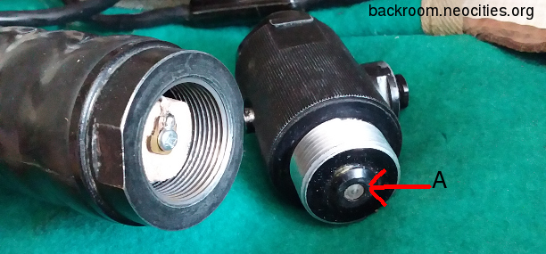
above: View showing power switch, with physical connector at point "A"
The power switch works by physically distancing the grounding connector (point A in the picture above) from the end of the last battery in the series circuit (or single 18650/spacer). If your spacer has protruding terminals like the one I made, it's important to make sure it goes in the detector FIRST. The battery disconnector needs a flat surface (the -ve end of a cell) to disconnect from, and if the spacer goes last, its screw terminals will simply continue to push into the recessed disconnector housing. In fact, the pressure from the battery/spacer combination will probably force the power switch physically off anyway, although it won't power off the detector as the protruding terminals will still be making contact!
Home Go back.